These simple wiring layouts are stripped of any project material so they may be seen clearly. Once you have the basics, you can build a wide range of projects. This is part 2.
- Part 1 covered the basics for small-scale projects. –> Return to Part 1
- Part 2 describes expansion capabilities using more of the same boards
In part 1, we described how one of each board can be used separately or together
In part 2, we will add more of the same boards
Covering these capabilities:
- A chain of Dittos
- Multiple chains
- Power sources
- A master brightness control
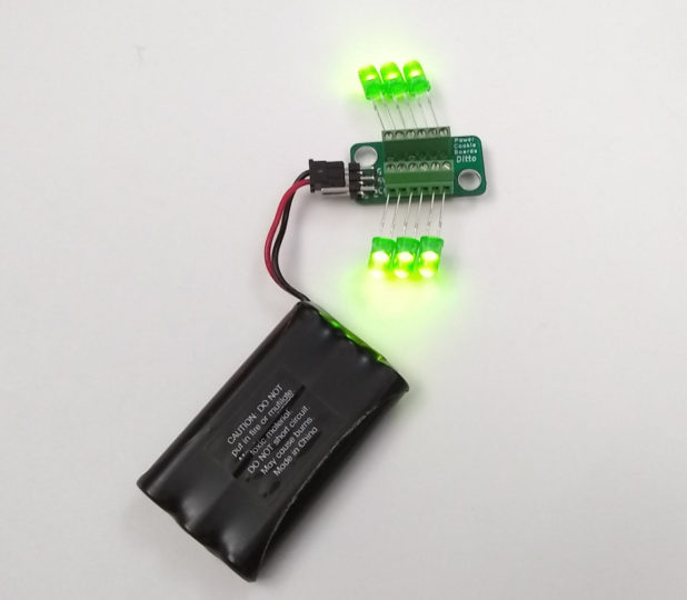
We’ll make a chain of boards: Two Dittos.

Now you see why every G/5V/CC connector contains two identical rows: To pass the same signals down the chain. Each Ditto shares these signals via Chaining Cables, which means they perform exactly alike.
It’s as if we have a double Ditto board with twelve LED’s all acting the same.
We can chain 100 Dittos together before needing a repeater. With repeaters, there is no earthly limit to how many Dittos and therefore LED’s we can drive from one Light Valve. Every 10 to 30 boards, we may need to insert more power, too.
We’ll cover simple Power Injectors and repeaters at some point, but not here. Until we do, know this: Any board with USB power can act as a USB power injector and any LED Port outputting that signal can act as a repeater.
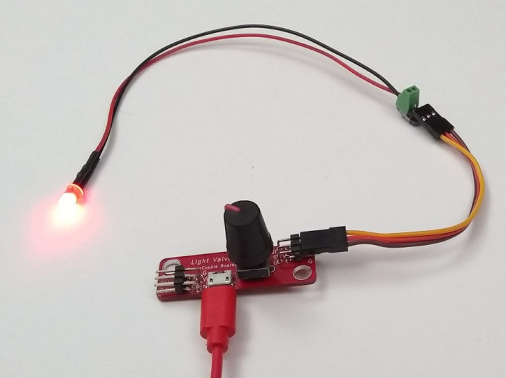
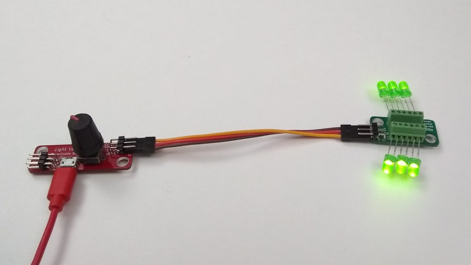
Let’s explore the upstream direction, the Light Valve’s left connector.

When two Light Valves are connected end to end, they both control the dimming of the chain of LED’s. We consider the left one as the the Master Brightness Control. Think of the right one as a kind of valve, much like a water valve, blocking part of that brightness depending on how much the knob is turned down.
Since the leftmost Light Valve was set at 50%, the LED’s are less bright than they were in the previous image.
An interesting point is that the CC input pins all operate alike, whether they be on Light Valves, Dittos or Morsels. That means we not only can chain 100 Dittos together, but also 100 of any mix of the three boards. We’ll use that fact.
That’s the basic concept. Let’s make it useful.
Two chains with a master control.

The leftmost Light Valve is now a master brightness control for the entire project. In addition, each chain has individual brightness control.
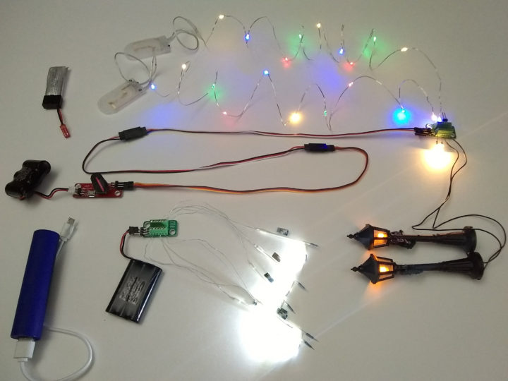
The upper chain of yellow LED’s is dimmed by one Light Valve. As we said before, that chain can be really, really long. Thousands of LED’s, really any quantity. Ditto for the red LED’s!
We provided two USB adapters (the black and blue USB cords) and have isolated their power apart from one another.
The Power Isolation Chaining Cable (the vertical cable with two wires, one white, one black) blocks 5V but passes G and CC signals. This allows master dimming information to be shared but keeps 5 Volts separated.
There are two reasons for multiple USB adapters. One is simply for more power. The other is to eliminate a faint flicker which may appear in some cases. This occurs with all digital dimming, so each Ditto contains a circuit that works to eliminate it. But it can’t for all combinations of LED’s, voltage and wiring choices, while isolated power can. Because a USB adapter is low cost, it is reasonable to plan for it, then eliminate it when not needed.
One key advantage of digital dimming is consistency: Analog dimming circuits don’t dim all color LED’s uniformly. The Light Valve does. This means you can mix up colors anywhere, even on the same Ditto and get them to turn off or dim by the same percentage.
We need this key advantage, particularly with a Master Control that is supposed to dim everything together.
If we do not need two USB Adapters, this is the result.

With one adapter removed, we need to connect 5 Volts across all boards. In place of the Power Isolation Chaining Cable, the vertical cable is now a Chaining Cable.
Next we trim the budget without affecting performance.
We eliminate a Light Valve.
And power it with two adapters…

Or one adapter…
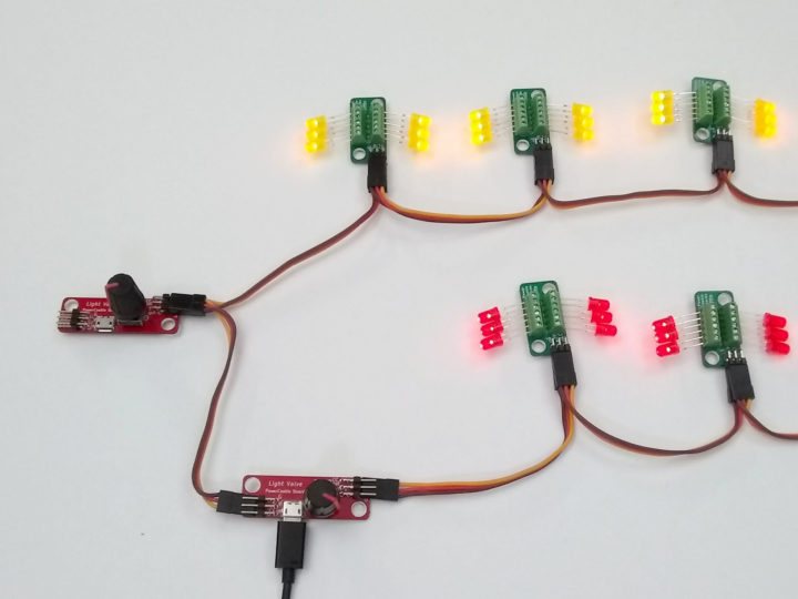
The Light Valve at upper left serves a dual purpose. It is the Master Control for the whole project. But it is also the control for the chain of yellow LED’s. The lower Light Valve controls just the red LED’s but is further dimmed by the Master Control. This can work because frequently, one chain needs to be brighter than the other(s). Cost is reduced.
Tip: For boards wired together, try to keep all power adapters on the same outlet or power strip. This avoids voltage differences that different outlets can introduce.
What a great place to end. We built a complete capability and ended on a cost reduction!
Conclusion
We considered a lot of setups. It is nice to know that no matter how big and complex the project, there is always a point further left where you can tie everything together with a single master control.
What next? Build a system. If it’s a large system, bring up each section, then tie them together. Don’t worry about accidentally shorting outputs or reverse polarity on Chaining Cables or LED’s. No damage is done, so reconnect and try again.
The flexibility found here means you don’t have to plan every last detail before building begins.